Friday, January 5, 2024

Kitchenaid Oven Repair

Disclaimer: I am not electrician and working with electricity can be dangerous, even fatal. All information shared here is for educational purposes only. Caveat emptor!

Oven model KitchenAid KEBS107 DSS 10

Short Version (TLDR)

The short version of this story is I re-soldered resistor R1 on the control board and everything seems to work fine now. How did I know component R1 was bad? When I touched it with my finger, it wiggled back and forth – it was evident the solder joints had failed. All of the other components seemed to be okay, although many appeared to have been running rather hot over the years.

Backstory

My KitchenAid wall oven has been working intermittently for some time, and recently decided to stop working altogether. In the past few months, it seemed to stop working periodically with no warning; or it would just cut out (even when it was not in use) and show the PF error (Power Failure).

In my mind, all of this pointed to some sort of loose wire or failing component on the circuit board. I’m not real good with circuit boards, but I have a bit of experience with them…and can spot a burned component, so with that bit of confidence I decided to attempt a diagnosis and perhaps a repair.

Internet research provided very little help. Usually the diagnosis was “replace the control board”…well, if I do that, I might as well replace the entire oven. The prices on boards were $250-$600 and we purchased the oven second hand several years ago for less than the current price of a replacement board, so instead of investing in a control board and crossing my fingers that it would solve the problem, I’d rather just find an “open box” oven or return at one of the big box stores and have a new oven with a warranty. But what I most wanted to do was to NOT spend $1000 (or more) on a new oven…and, if possible, keep this oven out of the landfill. Can you tell that I’m frugal? I tend to like my money and prefer to keep it in my pocket if possible (I’m generous too, but I have to have money to be able to be generous, so why purchase another oven if I don’t have to?).

Repair

First, I shut off the power at the breaker and checked for power at the oven using an inductive probe. The power cable supplying electricity to my oven is accessible in the cabinet under the oven, so I just held the probe near the cable and it didn’t beep, which made me feel confident that the line was not enbergized. This video shows how to use an inductive current tester, similar to what I used.

I then opened the electrical junction box in the cabinet and disconnected the oven eletrical wires by removing the wire nuts, which released the wire and the flexible conduit that connected to the rear of the oven. This had to be done because the conduit/wire acted like a short tether, preventing the oven to be fully removed from the wall cabinet. This video shows how to wire a junction box for an appliance.

Please be aware – electric ovens operate on 240VAC which is enough to kill a person – so I had to make certain the power was off. If I had been unable to confirm the power was off, then I would not have attempted this repair. Instead, I would have hired a qualified electrician or technician to make this diagnosis/repair.

Once the power was off, I opened the oven door and removed the screws holding the vertical trim on either side of the oven (one short screw on each side near the oven door hinges). After removing the trim by pulling down and then out, this exposed two more screws (one on each side) that hold the oven to the wall. I removed those screws. This video shows the location of the screws.

At this point the oven was able to slide out of the cabinet, but is rather heavy and bulky, so I employed the assistance of my son and the two of us pulled the oven out and set it on the kitchen counter (we placed a piece of corrugated cardboard on the counter to prevent any scuffs from occurring to the countertop). So far, so good.

The next challenge was to remove the top and back covers from the oven. There are several sheet metal screws that hold all of this together. I removed each screw from the top and placed it in a specific location so I wouldn’t lose them or get them mixed up with the other screws. I did the same with the rear panel, keeping the screws separate just in case they were different. Fortunately for me, all of the screws were the same.

In the top of the oven was the technical troubleshooting guide. The paper was brittle from age and heat. The scanned pages are at the end of this post, but there was nothing in the guide that assisted me with this repair.

Although this repair only required removing the top to gain access to the control board, I saw on YouTube where a gentleman checked a thermal switch on the rear of the oven, and that switch is under the rear panel, so I removed the panel, checked the switch (which was working fine, but it was missing a screw, so I added that screw) and then replaced the rear panel.

The control board is at the front of the oven held on with five screws. Looking at the components I could tell that many had been running hot for some time – the brown streaks going up (against gravity) indicated that heat and/or dust had been at work for several years.

I touched each component to see if it was secure and intact. The large resistor, R1, caught my eye and when I pressed on it, I could feel how loose it was. No other components were loose. Evidently the heat generated by the component in such a warm environment caused the failure of the solder joints and perhaps the circuit board traces.

I removed the ribbon cable by releasing the connector - on mine I had to pull up on the outer-band of the plastic connector. I had to be careful with this because the ribbon cable is just a strip of plastic with copper strips embedded in it (connecting the oven keyboard to the control board). The other connectors were more difficult to remove and the connectors with the heaviest wire did not release, so I left them connected and just made my repairs while the board was attached to the oven.


I removed the five screws that held the board to the front, being careful to not lose the spacers holding the board away from the oven face. Also, the displays are plasma, which are made from glass, so I had to be very careful to not break them. A crack in the glass and the display will go out (why don’t manufacturers just use LED/LCD displays?).


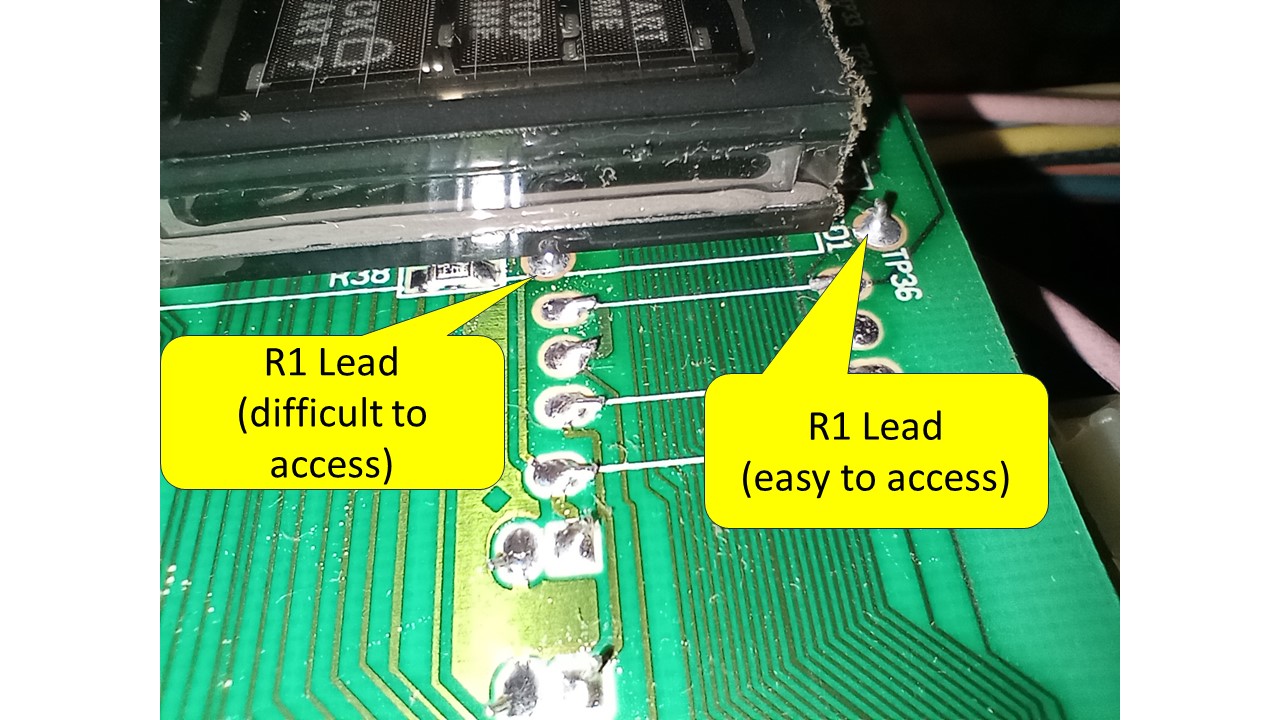
Now here’s the tricky part: one lead for R1 is at the top of the display (fairly easy to access) and the other is under the display (virtually impossible to access). I tried just resoldering R1 and that worked on the lead under the display (I was able to get the tip of the soldering iron to touch the lead of R1 and dab a bit of solder on it; I also tried to add some solder from the component side).


On the lead that was easy to access I attempted to resolder it without success – R1 still moved. Using a simple multimeter on the ohms (resistance) setting, I determined where the leads of R1 connected to – the top lead connected to the first pin on the display. With that bit of important information, I took a short length of wire, bent an eyelet in one end to go around the R1 lead, and bent an “L” in the other end so it would lean up against the first leg of the display (no photo for that, sorry). Then I removed the solder from the R1 lead with a solder sucker (a hand operated vacuum device – some copper braid would likely work as well), and the placed the short length of wire in place, and soldered both ends – the eyelet end soldered to R1 and the “L” soldered to the display leg. Then I dabbed a bit of solder on the component side of R1 (in the unlikely event that this is a multilayer PCB). I checked for a solid mechanical connection (no wiggles) and then placed an ohmmeter on it – the continuity seemed fine. It seems we had success.

After that I buttoned it up – reattached the control board to the face of the oven (spacers and five screws), plugged in all the connectors, vacuumed the dust from the top of the oven, placed the tech sheet back in the top, reinstalled the top and the back panels. Then I rousted my son to help me lift the oven back into the cabinet hole, and reconnected the cables/wires. Flipped the breaker to the on position, everything seemed to work fine. So we shut off the power, finished screwing the oven back in the wall, replaced the trim pieces, placed the cover on the junction box, and reapplied power. It still worked – yea! I set the oven’s digital clock, cleaned up my mess, and enjoyed an adult beverage to celebrate keeping another appliance out of the landfill.


Now, with all that being said and patting myself on the back, I do realize that it is highly likely that the control board will fail again in the future – it is exposed to too much heat and the components are likely to fail when the ambient temperature they are exposed to while the oven is operating is 120F-200F. It’s just a poor design by the manufacturer . . . and I suspect that with a bit of engineering the oven could be designed to either (a) keep the board a bit cooler or (b) use oversized components on the board so they will last longer in this harsh environment. I realize that goes against planned obsolescence, but it would create less waste in the landfill. Honestly, I wish I could find an oven with knobs and mechanical thermocouples rather than this electronic crap we seemed to be forced to purchase today…just my $0.02.


Cheers!

Tech bulletin found in oven

Monday, March 25, 2013

HTX-10 Mic Audio Repair

I purchased a HTX-10 10-meter rig off ebay a few years back and found that the microphone audio was VERY low. Signal reports were that my audio sounded very muffled, like RF was getting into my power supply. It turned out that the L404 was bad. A big "thank you" goes out to KJ4LTC for his suggestion of this fix (posted here).

After making my repair I thought it might be helpful if I posted some photos of the process, as I'm sure that others have experienced the same problem.

First I opened the rig. Remove the bottom panel and be careful to not rip out the speaker wires--you'll need to disconnect the speaker by pulling on the connector.

L404 is located on the front panel PCB and is placed between the on/off switch and pin #6 of the microphone.

Here is the general location of the culprit:

...and here is the specific location of L404 and my "repair":

In my case I took a small piece of (blue) wire wrapping wire and wrapped one end around the switched side of the on/off switch bare wire and then wrapped the other end around pin #6 of the microphone connector, then soldered both connections. This solved the problem!

Prior to making this repair I struggled to diagnose this problem because I was running the radio off of a computer power supply (CPS). I read in several places online where people had successfully converted a CPS to use for hobby purposes and even to power radios, but it didn't work for me. As soon as I hooked the radio to the CPS the voltage dropped to <12v and when I transmitted it was in the 10V range--certainly unacceptable for diagnosing audio issues. I thought that might even be the cause of the audio problems, so I finally built a linear PS from a automotive battery charger and had a supply that would yield 13.7v no load, and 13.1v under transmitting load.

With a good PS I could begin trouble-shooting the radio to diagnose the problem. One way I did that was by injecting signals into the mic input using a pig-tail, which worked well, but of course was unnecessary. A DVM was all I needed :-)

Here's a picture of the pigtail:

The other repair I made at the same time was reconnecting the ground from the front PCB to the radio frame. The factory had soldered the ground wire to the frame, which broke loose. I decided to not try to resolder it, but to rather just add a crimp connector and bolt it to the frame.

If you're worried about transmitting with full power during the diagnosis and repair, just remove jumper to lower the power of the rig. This allows you to transmit at minimal power(<1watt?), which may be beneficial if you are using a low amperage PS.

Jumper location on PCB:

Jumper location:

Jumper removed:

Good luck with your repair!!

~Doc

Monday, December 31, 2012

Stinky Washer

While repairing the brake on my Maytag Performa washer I noticed a distinctive "sour" odor emanating from the washer. In the past my wife had mentioned that the washer smelled sour or musty and to alleviate the odor she would keep the top on the washer open when we were not using it, in an effort to "air it out." But it always seemed to me that a washer shouldn't need to be "aired out." I never remember my mother or grandmother "airing out" their washers; the lids were always closed. In fact, my grandmother's washer was in her kitchen and she used the top of the washer as additional counter space!

While I had the tub removed from the washer to make the brake repair I noticed a lot of dark material around the top of the tub, located between the basket (the perforated basket in which you place your clothes) and the external tub (the part of the washer that contains the water). Further investigation determined that this dark material consisted of dried on lint and dirt from the clothes. Evidently, as we wash our clothes a form of "bath tub ring" forms around the top of this tub. Over the years the material accumulates and forms a thin layer of "gunk" washed from our clothes; primarily lint, dirt, and soap. I suspect it is the soap that acts like a glue to hold all of this in place.

I just imagined how this layer of material would hold water and over time begin to harbor that musty smell which my wife complained about. Since the tub was out of the machine, it seemed like a rather convenient time to clean this gunk form the tub.

Before we go any further, let me take this time to add my disclaimers:

Disclaimer #1: The information posted is for informational use only. Use it at your own risk as the statements on this page may be completely wrong, or your washer may not be like mine, or your mechanical skills may be rusty, or...well, there are myriad reasons why you shouldn't attempt this repair or the information may not be valid. Caveat emptor!

Disclaimer #2: Unplug your washer before working on it. You don't want any electricity to be present when you open the cover on the washer and begin poking around on the inside.

The ideal thing to do would be to wash off the gunk with a high pressure water stream from a garden hose or perhaps a car wash. However, I had already installed the brake on the tub and didn't want to that wet. Also, it was rather cold outside--too cold to run a water hose comfortably--so I decided to scrape the material from the tub while remaining inside the comfort of the washroom.

The first thing I had to do was remove the rim from the top of the tub. This rim just clips on, so using a putty knife and screw driver to pry it off worked well. I placed the putty knife against the tub and then placed the screwdriver between the blade of the putty knife and each clip of the ring. The putty knife prevented the screw driver from puncturing the side of the tub. Sorry I didn't take any photographs of this process :-(

I used a putty knife and a pocket knife, but you might find something more effective. My two main concerns were (1) puncturing the tub, which would produce a leak during the next use of the washer, and (2) making the smooth plastic tub rough, which would just speed the accumulation of gunk to the tub in the future. So, very carefully, I scraped the material I could get to with my knives, pulling it from the tub placing it on a paper towel (i.e., wiping it from my knife) so it wouldn't drop down into the bottom where it might cause further havoc.

After I scraped all I could, I took a spray bottle of 1 part vinegar and 1 part water and sprayed the remaining gunk and then wiped it out the best I could. This vinegar/water solution seems to be a good all-around cleaner when I don't want to use soap. Vinegar is a good mild cleaner and works on most surfaces: windows, doors, cabinets, etc. Also, I figured that the chemistry of the vinegar would offset the chemical composition of the soap: vinegar is a mild acid and soap is a mild base (remember your pH scale from high school chemistry?). Hopefully the vinegar would break down the surfactants in the soap and clean the plastic surface of the tub.

One thing to remember about soap is this: it is designed to attract dirt. This is a physical/chemical process that works very well. Unfortunately, once an item is cleaned, it is rather difficult to remove all of the soap from the surface. Many times, a bit of the soap remains, especially if water was not used to rinse the surface. So, any remaining soap tends to attract dirt quicker than would normally occur with a "clean" soap-free surface, therefore it becomes dirty quicker than previously.

This phenomenon occurs when you have your carpets cleaned or you use any of the household spray-and-wipe cleaners, etc. That soap residue that is left behind attracts dirt. However, when using the vinegar, no soap is used so no soap residual remains to attract dirt.

Once the majority of the gunk was removed I gave the tub a good spraying of vinegar/water and re-installed it back in the washer. I suspect that spraying the inside of the tub with the vinegar solution after using the washing machine will help prevent the build up of the gunk too. Another option is to add some vinegar to the washer and let it run through a wash cycle, but getting a 1:1 mixture of vinegar and water in your tub will require several gallons of vinegar, which is probably not cost effective and could damage the washer pump or other components.

Happy fixing!

~Doc

Wednesday, December 26, 2012

Maytag Performa Brake Repair

UPDATE:It's been a year since I first posted this repair (see old post below). The repair lasted about a month then the washer brake started screeching again. Then this week I searched for some alternative repairs--looking for someone to confirm my suspicion that adding a bit of lubricant to the brake might alleviate the squeal. Eureka! I found a post, added oil to my brake, and the squeak is (nearly) gone! hooray! More will be added later, but the short solution is this: about 6-8 drops of 5w-30 placed on the brake did the trick. For more information see this link and scroll down about 3/4's of the page to Figure M-12 http://www.appliancerepair.net/washing-machine-repair-7.html. I removed my tub to do this procedure, but that may not be necessary.

ORIGINAL POST:
It was Christmas and I needed a project. Our Maytag washer had been making a high pitched screech at the end of the spin cycle that would make the hair on the back of my neck stand on end. It was the kind of sound that reminded me of someone dragging their fingernails across the chalkboard--but for just a second or two. Needless to say, everyone in our house was ready for the screeching to end! My solution was to clean the brake and--eureka!--the noise ended and I am back to being the hero of my castle.

Here's the story: As we all know, Google is the purveyor of all information, so engaged in a google search that led me to believe the problem was in the washer brake mechanism. Further googling yielded a discussion board posting that suggested adding a drop or two of oil to the brake to eliminate the squeal, with followup posts suggesting oiling the brake was a bad idea. Adding oil to the brake seemed like a poor solution to me too (I envisioned a sheen of oil on my car brakes and an inability to stop as I approached a stopped car in front of me). I felt their had to be a better way to address the noise.

More googling led me to Angel Acevedo (aka TheApplianceMan). This man has made some GREAT videos illustrating how to properly repair appliances. His video about the Performa brake gave me the confidence that I could tackle this project (watch it here http://www.youtube.com/watch?v=0HUbV4mxyYE). But instead of replacing the brake ($32-$50) I decided to repair the brake and now the screech is gone!

I'll share the step-by-step instructions for making this repair, but you need to watch Angel's video too for the complete story and instructions. I'll mainly focus on how I cleaned the brake. Before you begin, here are my warning and disclaimers:

Disclaimer #1: The information posted is for informational use only. Use it at your own risk as the statements on this page may be completely wrong, or your washer may not be like mine, or your mechanical skills may be rusty, or...well, there are myriad reasons why you shouldn't attempt this repair or the information may not be valid. Caveat emptor!

Disclaimer #2: Unplug your washer before working on it. You don't want any electricity to be present when you open the cover on the washer and begin poking around on the inside.

Disclaimer #3: Some of the photos are terrible. I used to be very critical of some of the out-of-focus pictures I saw on the web, but now I understand why they are so bad: Trying to get a close up shot, using only one hand, while holding the part being photographed with the other hand, is a feat!

Let's get started! The first thing is to remove the belt from the pulleys on the underside of the washer. Next you'll remove the front panel of the washer--you'll need a putty knife and a 5/16" (or 8mm) wrench or nut driver to get the front off of the machine. See Angel's video (I told you to watch it!). Slide the putty knife under the front of the top and push on each side to release the spring clips. After that, remove the two 5/16" screws holding the front panel in place.

Next you'll remove the springs holding the tub in place--I used a vice-grip to remove the springs, but you may have a better idea or you might even have the $20 spring remover that Angel uses on his video. Let me share this with you: the front springs are MUCH easier to remove than the back springs. In fact, you might want to remove the inspection plate on the rear of the machine to access the rear springs(see photo below). Also, you'll need some strength to remove these springs, or at least some leverage (physics at work!).

Remove the two hoses attach to the tub: the water fill sensor (small clear (or white) hose on left-hand side of tub) and the drain hose (large black host at bottom on right-hand side). The drain hose clamp might be accessed easier from the rear through the inspection panel. Have a towel or two ready when you pull off the drainage hose because all of the water still in the discharge host on the discharge side of the pump will spill on your floor--probably a half-gallon of old rinse water. My water had a sour smell, so be forewarned.

Find a helper and remove the tub from the washer lifting straight up (watch Angel's video), set the tub upside down so you can access the pulley and brake, and then remove the pulley and all the hardware (see Angel's video). I set a towel on the floor to absorb any residual water and not damage the tub edge. As you remove the C-clip and washers be certain to place all of these pieces in the exact order they are removed so that you can replace them in the correct order later. Also, be certain to place them correct side up too.

Now on to the brake--this is where things get tricky. Removing the break drum can be problematic because the there is a 200 pound spring under the drum. You can easily damage the drum if you're not careful.

To remove the drum, remove two screws opposite each other, just like Angel does. Then replace these screws with two 1.5" 10-24 screws. The 24 threads-per-inch worked on my washer, so I suspect yours is the same. Angel used self-tapping sheet metal screws, but a machine screw will keep your threads intact.
Once you have replaced the two screws with the longer replacement screws and tightened them down, then remove the four other screws. After that you can slowly unscrew the two long screws, backing each one out a little at a time (see Angel's video) until the pressure is off the 200 lb spring (that's right--200 pounds!). If you just start removing all the screws one at a time you'll ruin the brake drum and have to purchase a new one.

The brake has two parts: the drum and the shoe. The drum is on top and is what you see in the picture below. The shoe is underneath with a strip of brake lining attached to it. My lining had a 3/8" space between its beginning and its end, which appeared to be normal (see photo).

Remove both parts from the washer. I noticed that my parts were covered with a fine powder--a dust--presumably from the brake lining. At this point I placed the drum over the shoe, like they would be on the washer, and attempted to recreate the noise by twisting these two against one another--which I did, not quite as loud, the vibration did start to occur which produced a lower pitch, similar to the sound you get when rubbing your finger around the edge of a wine glass. Problem identified!

Take both pieces to your workbench and wipe down with alcohol to remove the dust. I don't know what this material is made from, but it's probably not a good idea to just blow it off the drum. This is probably all that is needed to stop the screeching because at this point I tried to recreate the noise again and no noise--hallelujah!

Not wanting to venture into the washer again and fight those tub springs, I decided to take an extra step and "resurface" the brake and shoe. As you can see from the photo a very shiny worn surface was evident where the brake shoe had rubbed against the drum for the past 10 years. To resurface this area I took a small piece of 215 grit sand paper (any fine sand paper should work) and made one or two passes across both the drum and the pad. I then wiped both parts down with alcohol again.

This is how the drum looked after "resurfacing" it.
One last thing I did was vacuum the plastic dust and threads that had worn from the plastic ring at the base of the tub ("snubber ring"?). I also vacuumed the plastic shavings and dust from the bottom of the washer.

Assembly is opposite of disassembly. One caution: When reattaching the brake assembly on top of the 200 lb spring, begin with the 10-24 1.5" screws. Carefully get the threads started into holes opposite each other. Then slowly screw down each screw a little bit at a time--one side and then the other--until the two 1.5" screws are tightened down all the way. Then replace the other four screws. After that, remove the 1.5" screws and replace them with the original short screws. (Once again, watch Angel's video).

The rest is relatively easy: replace the washers and other hardware in the same order that it was removed.

Here's where I took a detour: We cleaned the gunk from around the top of the tub. See my other blog post for more information about that procedure.

Back to the reassembly. Two people are needed to set the tub back inside the washer. Be careful to set the tub down very slowly and seated on the bottom of the washer properly. The tub label should face towards the front of the washer.

The most difficult part of this procedure was re-attaching the springs to the bottom of the tub. For each spring, place the bottom hook in first, and then stretch the spring to attach the top hook to the bottom of the tub. Place the rear springs on first--they are the most difficult to get to and it's easier to re-insert these springs when the tub has some ability to wiggle back and forth. Also, accessing the spring mounts from the back of the washer may be easier.

In my case I was able to replace all of the springs through the front of the washer, beginning with the rear springs first, and working towards the front. I used locking pliers (aka Vise-Grips) while laying on the ground in front of the washer with my arms inside the washer, all the while developing a new vocabulary as the springs slipped from my pliers. Only twice did the pliers slip with such force to cause my fingers to hit the base of the tub, yielding a loud "ouch!" and bruising my pride more than my fingers.

Re-attach the hoses (there are two: a slender fill sensor hose and the large pump drain hose). Be certain to double check the clamps for these two hoses or you will be mopping up a mess later.

After that, replace the front of the washer and plug in the cord. Test you handiwork by running it through the delicate cycle on extra large load. Then listen for the end of the spin cycle--hopefully you'll be pleasantly surprised at the noticeable silent stop of the tub.

Good Luck!

~Dr. Fix It Follow-up: a few weeks after I made this repair the squeak returned, but not nearly as loud. So, a drop or two of oil silenced it once again. (And I do mean just a drop or two--be very conservative with the lubricant).

Sunday, July 31, 2011

Weekend Mechanic: Repairing 2000 Toyota Sienna Horn

TL;DR: By lubricating the ball bearings in my steering column I was able to restore the electrical ground connection, thereby making my horn operable once again. Evidently one of the components of the factory lubricant evaporates over time, causing the "grease" to become hard and brittle. Restoring some of the lubricity seemed to fix this.

Backstory:
For a year or two the horn on our 2000 Sienna has worked intermittently at best. Most days when I push on horn button in the center of the steering wheel I get no response. Of course this always occurs when I need the horn most...

So, after cursing the horn on numerous occasions, I finally broke down and decided to attempt the repair. You know, when I was younger working on vehicles was something that intrigued me, but now that I'm on the backside of 40, I no longer get the same sense of excitement and adventure as I once had--The feeling I get now is that sinking feeling in my stomach, thinking, "there are so many other things I would rather be doing than twisting wrenches." Yet, because of my frugality, stubbornness, and "I can fix it!" attitude, I dutifully enter the garage....

So I pulled the Haynes manual, found the wiring diagram, and went to work. I pulled the cover from fuse & relay box under the hood and checked the fuses: all were good - check. Then I pulled the horn relay and tested it using the battery: it clicked when energized - check. Next, with the relay still pulled from its socket, I ran a jumper across the receptacles in the relay socket and the horn blasted loudly - check.

This led me to believe the trouble was between the steering wheel horn pad switch and the relay. A Google search revealed that there is no wire that grounds the steering wheel to the frame, but that the steering wheel is grounded via bearings. According to online sources (i.e., discussion boards, see this link http://www.automotiveforums.com/t894269-sienna_2000__horn_works_only_when_car_is_not_moving.html) the grease lubricating the bearings dries over time, coating the bearings in dry lubricant, which acts as an insulator. This dry grease prevents the flow of electricity from the steering housing, through the bearings, to the steering wheel. To remedy this situation you just have to lubricate the bearings. Simple! But where are these mysterious bearings? Discussion boards stated they were near the top of the steering wheel, but no photos existed. So, to help other frugal weekend mechanics I am posting photos of the bearing location here. In fact, I'll post photos of the entire process. This took me about an hour to complete the entire process.

A few disclaimers before we get started....

Disclaimer #1: The information posted is for informational use only. Use it at your own risk as the statements on this page may be completely wrong, or your vehicle may not be like mine, or your mechanical skills may be rusty, or...well, there are myriad reasons why you shouldn't attempt this repair or the information may not be valid. Caveat emptor!

Disclaimer #2: Let me say that I know my van is dirty, which is documented in the pictures. The past two places we lived had red clay soil, which stains on impact. There are also three teens in my family and occasionally our pet golden retriever rides with us, especially when we camp, so yes, we use our vehicle and it doesn't get cleaned nearly enough...surely I am not the only person in America with stained carpet and dirt on their floor (I did vacuum the van after these pictures were taken--out of guilt).

Disclaimer #3: Some of the photos are terrible. I used to be very critical of some of the out-of-focus pictures I saw on the web, but now I understand why they are so bad: Trying to get a close up shot, using only one hand, in a dark van, while holding the part being photographed with the other hand, is a feat!

So, here goes....

First, disconnect the battery. Doing this will allow you to use an ohmmeter without worry of finding a voltage by accident (which could be devastating to your meter). This will also prevent the airbag from exploding in your face, an event that would ruin your day.


Second, check the horn steering column to see if you have a good ground. This will help diagnose the problem to make certain that the effort you exert for this repair will be a good investment.

Connect your ohmmeter to a good ground. I used a battery clamp attached to the lighter plug and accessory plug (see photo). Any metal part of the car body will do for a ground, but finding a metal part on a plastic car can be difficult...


Next, check your steering column for ground. To do this make certain your meter is properly operating and connected to ground by shorting the meter leads and noting the zero on the meter. When the leads are not touching the resistance (ohms) should be infinite. With one probe connected to your "established" metal ground (the lighter plug, in my case) probe around on the care body to find another metal spot that is ground. Once you know that you have a good ground connection you can check your steering column for ground (i.e., conductivity).


To access the metal in the steering column I took a short piece of copper house wire and wrapped it around the probe tip to make a "probe extender." Take the extended probe and insert it into the narrow space between the steering wheel and the steering column. This is the only piece of metal I could find that was easily accessible (click on the photos to see a larger picture).


When you touch the extended probe to the metal at the base of this narrow gap, it should read zero ohms (i.e., it has a good ground). If you get a reading that shows resistance, then there is a good chance the problem lies in those pesky bearings. (note: the photo shows the steering column with the covers removed. You don't have to remove the covers to access this area).


Okay, now that you've determined your steering wheel is indeed not grounded, let's get those bearings greased and see if that solves your problem.

Remove the covers from the steering column. To do this you will need to first remove the kick plate, door jamb panel, and "panel sub assembly" (I don't know the correct terms for these items, so I'll describe each piece the best I can). The kick plate is the plastic cover that is adjacent to the carpet on the floor and is covered when the door is closed. Gently pull on it with some force and it will give way. I slowly pulled mine by getting my fingers underneath it on the seat-side and slowly tugging at it, trying to be careful to not break any plastic "trim retainers" hiding underneath.


Next remove the door jamb panel (this is the panel that covers the lower area of the door jamb next to the emergency brake. You'll need to removed this to access the left side bolt of the panel sub assembly). Just gently pull on this and it should come loose, being careful to not break any plastic "trim retainers" hiding underneath.


Now you can remove the lower part of the dash called the "panel sub assembly" (where coin holder is located). To do this, remove the 10mm bolts on each side of the panel sub assembly and then gently pull the piece down. You'll notice the tire air reset button is located here. I used a small flat-head screw driver to disconnect the wires from the button so I could lay this panel on the floor


You're almost there (this all sounds much worse than it is. It was really a pretty simple job, except for the 95 degree temps and 50% humidity). Next take a Phillips head screw driver and remove the three screws holding the steering column cover in place. One screw is directly under the steering column (easy to get to). The other two are located on the left and right side of the steering column, directly under the steering wheel (odd places to have a screw). To access these two you will need to rotate the steering wheel 90 degrees to the right to access the left screw and then, beginning at center again, rotate the steering wheel 90 degrees to the left to access the right screw. At this point the bottom half of the steering column cover should drop to the floor and the top should be able to be lifted up (but probably not come completely off).


Now you can see the guts of this beast. The bearings you're looking for are here (click on photo for more detail):


To clean and lube these babies use a spray lubricant with a straw (tube) stuck in the nozzle and a rag held underneath the steering column to catch the excess lubricant.


I began with some electrical contact cleaner spray. That seemed to do no good, because after spraying it into the bearings I still measured "infinite" when I placed the extended probe at the steering wheel. From there I changed my course of attack and used a multi-purpose lube (see comments below for other suggested lubricants, such as a copper lube), and this worked. I sprayed, rotated the steering wheel 90 degrees, sprayed more, rotated back the other way 180 degrees, sprayed more, etc., all the time holding a rag underneath the steering column to catch the lubricant that was trying to drip on to my "sub panel assembly" sitting on the floor (note: one reader said that on some vehicles (not a Toyota), rotating the steering while the engine was not running damaged the power steering seals. I didn't have that mishap occur, but caveat emptor!)

Another check with the ohmmeter showed that the steering wheel was grounded...yippee! I reassembled the dash, hooked up the battery--which set off the car alarm, so keep your remote for your alarm handy. I then pushed on the steering wheel horn and wha-la, it worked!

After looking at the filthy floor of the van for the past hour I decided to break out the shop vac and vacuum the front half of the van, leaving the remainder for my children to clean.

Good luck with your repairs. If anyone has other tips please share.

-Doc